
I presented my Interactive Installations final project last week! I’ve named it Lights, Camera, Magnets since it uses… lights, cameras, and magnets. (And a projector). Here's a video of my classmates interacting with this piece during my final critique.
Summary
Lights, Camera, Magnets invites users to manipulate a neon tube of light via magnetic paddles. By dragging the magnetic paddles underneath the table, the neon tube wiggles around. The neon tube is sitting on a dark surface, with a ceiling-mounted camera and projector pointed towards it. The camera sees the neon tube’s motion and project’s a motion trail/ripples onto it.
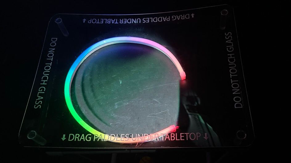 Example of light ripples from the tube projected down onto the table
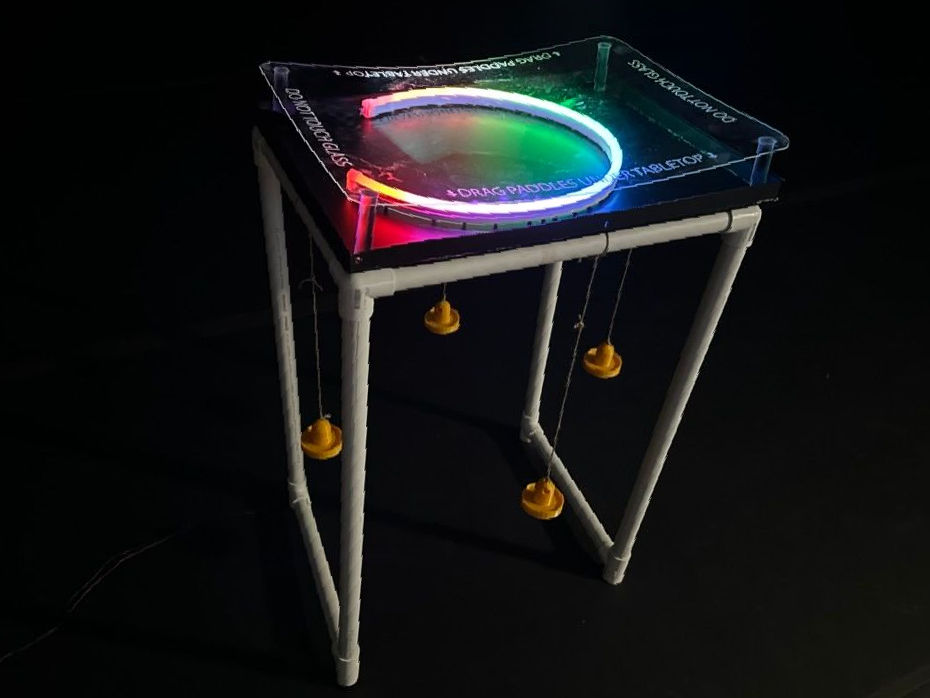 The whole table structure, installed in a dark space
How It Works
I mounted a projector and a webcam to the ceiling grid, both pointing at the neon tube on the table. They were mounted close together so that their fields of view overlapped as much as possible. A Max/Jitter patch receives the live camera input and does some processing on it to ignore background noise, increase contrast/saturation, etc. The projector receives this processed video stream and projects it onto the table, causing the camera to also see the projected output. This creates a feedback loop, since the camera and projector are affected by each other.
 The projection feedback loop makes it look like the tube is expanding out from itself
This already created some cool visual effects, but I wanted the image of the projected neon tube to line up almost exactly with the physical neon tube on the table. I wrote another patch to give me further control over the camera-projector alignment. The patch shown below controls the horizontal/vertical offset and zoom for the camera feed.
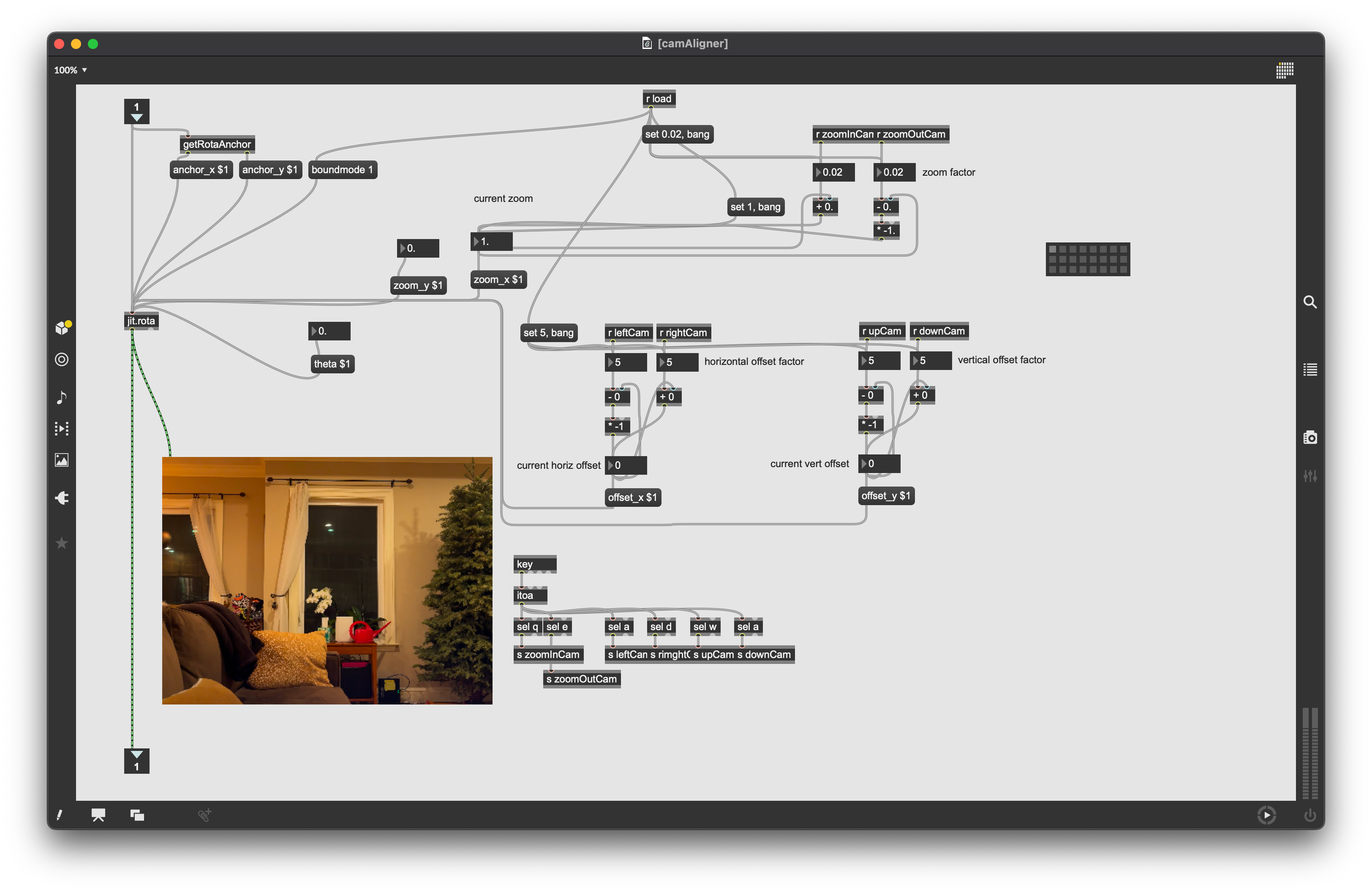 The camera aligner Max/Jitter patch that I wrote to help with installation
This helped me control for varying distances between the table and the ceiling-mounted camera, and let me crop the camera feed exactly to the edges of the table. I did the same for the projector, and kept tweaking all of these variables until I could see things lining up.
Here I'm adjusting the projector zoom variable, so that the projected image is shrunk
That's pretty much the extent of the software for this project. It was much less technically complex than my midterm project.
Fabrication
This project might have been less technically complex than my green screen midterm project, but it had so much more to fabricate:
- A portable PVC pipe table frame with a dark tabletop
- An acrylic cover to prevent people from touching the tube with their hands, while still giving me access to the wiring when I needed. I used a laser cutter to engrave instructions onto this cover
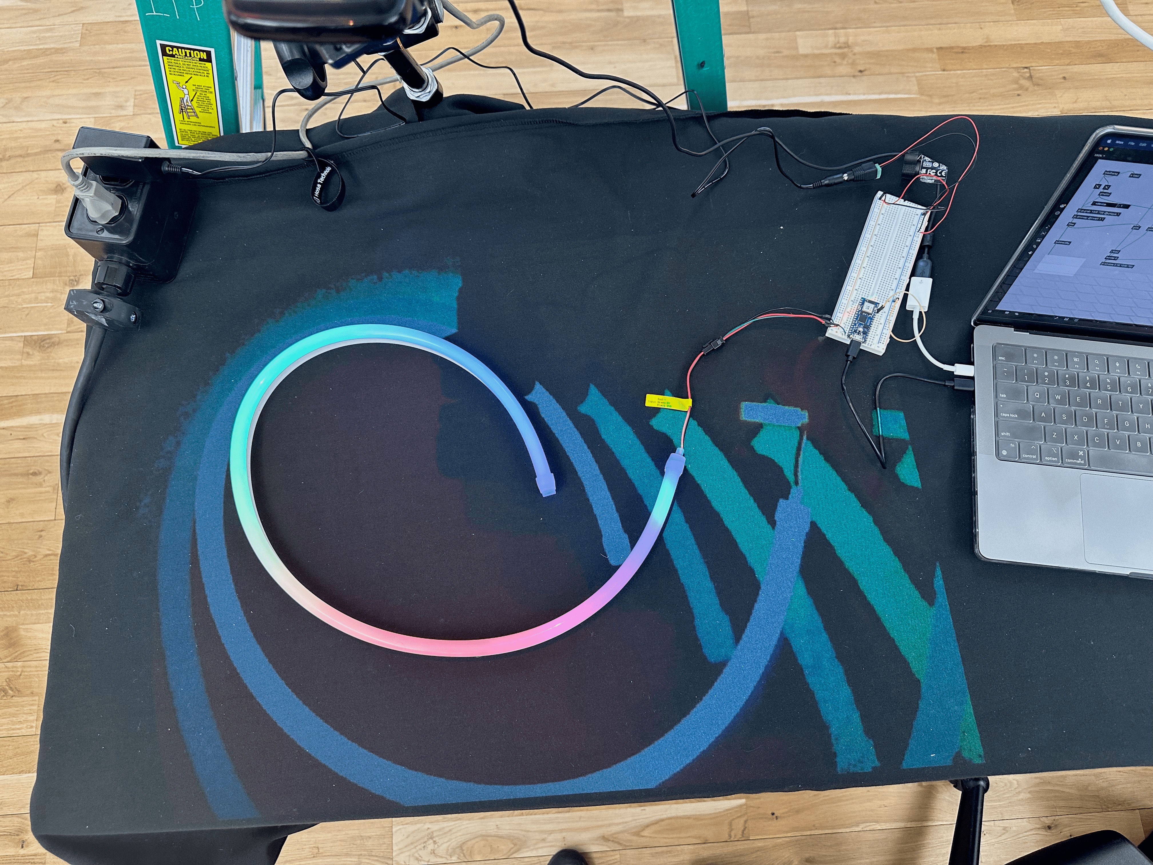
- Wiring for the neon tube. I may have caused a small circuit board explosion while figuring this one out
- Small magnets attached to the bottom of the tube
- 3D printed magnetic paddles tied to the table frame, to let people move the tube. Fighting undergrads for 3D printer time at the Tandon Maker Space during finals was Not Fun
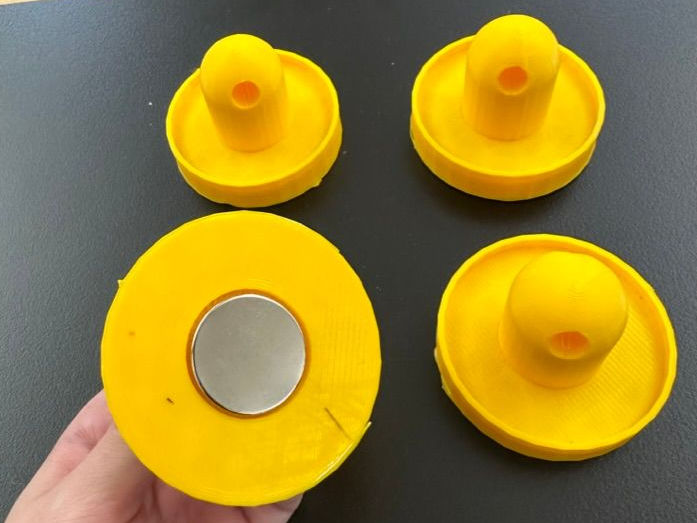 The 3D paddles I modeled and printed, with insets to hold Really Strong magnets
Successes
✅ Camera input + projector output alignment. Once the camera and projector were mounted to the ceiling, it was very tedious and physically difficult to move them. Aligning their inputs with the Max jit.rota object meant it was painless to make changes as needed, such as aligning after initial setup or when the table accidentally shifted
✅ Base fabrication. I was anxious that the table structure wouldn’t come together. It's just a rough prototype, but it got the job done. The engraved text on the acrylic cover looks fantastic
✅ Concealed wiring. I didn’t want messy wires to be visible on the base structure. It was surprisingly easy to route the neon tube’s wires down the PVC pipe table leg so that they could run across the floor. I also wrapped the top of the wires in black cloth so that they didn’t stand out against the black background and were invisible to the camera. This was just some black cloth + hot glue but it looks pretty good
✅ Playful experience. During the final critique I was happy to see that students were eager to engage with my installation. There was some interesting emergent behavior where students worked together to move the tube to one side of the table with their magnetic paddles!
Challenges
❌ Flakey wiring. My wiring had been pretty consistent until right before the final critique. There are a few factors that likely affected this: the table leg pressing on the neon tube wires, the long length of the wires, a short 12V power adaptor wire that could barely reach my breadboard, bad soldering, etc
❌ Table stability. Since this table was just made out of PVC pipe, it was very lightweight and not very stable. It was easily shaken by users playing with the magnetic paddles. A heavier table would make for a better user experience, but wasn't possible since I had to transport it between staging spaces every day
❌ Magnets. I tried 5 kinds of magnets attached to the bottom of the neon tube, but none were perfect. In the end I used decently strong neodymium magnets, small enough that they didn’t exceed the diameter of the neon tube so they weren’t visible. But these were barely enough to counteract the weight of the tube on top of them, and it was very hard to move the tube via the magnetic paddles through the posterboard. During the critique I dealt with this by giving users the chance to interact with and without the paddles. In the second half of the demo video, you can see that I removed the acrylic cover and encouraged users to use their hands
❌ Camera quality. The webcam I was using wasn’t great. Since it was so high above the table, it had a hard time picking up the colors emitted from the neon tube. I could’ve experimented with some commands in Max/Jitter to improve this, but I ran out of time. If this had been more successful then the motion trail/ripple effect would’ve been multicolored instead of just shades of blue
❌ Visual effects. While developing this project I had a variety of visual effects from the camera + projector + Max feedback loop, but the results were never consistent. It was very dependent on the lighting and camera/projector alignment. The final effect I had during my critique could’ve been more dynamic and engaging. Here's an example of an earlier visual effect I achieved:
This effect looked like there was a pool of water inside of the tube!
Reflection
I learned a lot from this project, particularly the importance of testing things as early as possible. I focused on getting my camera + projector + Max setup running ASAP, which was my #1 concern. However, I could’ve tested the magnets and the whole table setup earlier. I scrambled to build the table structure 4 days before my critique, so I couldn’t test the full magnetic paddle + magnets on the tube + moving through the posterboard until then.
This was my first time working with a projector or anything mounted to the ceiling, and I really enjoyed it. I now have some experience with different kinds of projectors and their capabilities, like zooming and focusing.
I got a lot of good feedback for how I could improve upon this prototype in the future, such as:
- Prompting users to engage with the piece while it’s at rest, such as a pulsating light around parts of the tube
- Building a bigger surface to work with, so the tube isn’t as constrained
- Having multiple neon tubes that can move independently, although with the ability to sync their lights
- Turning this interaction into a game
- Going further with the projector, projecting more than just a light trail since there’s so much more empty space to project onto
Equipment List
- InFocus IN1116 projector + power cable + HDMI cable
- Logitech HD webcam
- 2 Manfrotto magic arm clamps
- Neopixel RGB neon tube
- Arduino Nano IoT 33
- Breadboard
- 12V power adaptor
- Laptop running Max/MSP/Jitter
- 20ft PVC pipe + assorted joints
- 18″x24″ Acrylic sheet
- 4 acrylic dowels
- 4 3D printed paddles
- Neodymium magnets
- Lots of extension cords
- String
 All of my equipment rentals. As a software engineer, this terrified me