
Another semester, another round of Jello based projects. I launched two new Jello projects in the past few weeks, and somehow neither of them were for my class on soft things...
First up is my musical Jello printed circuit board.
DJELLO 2.0
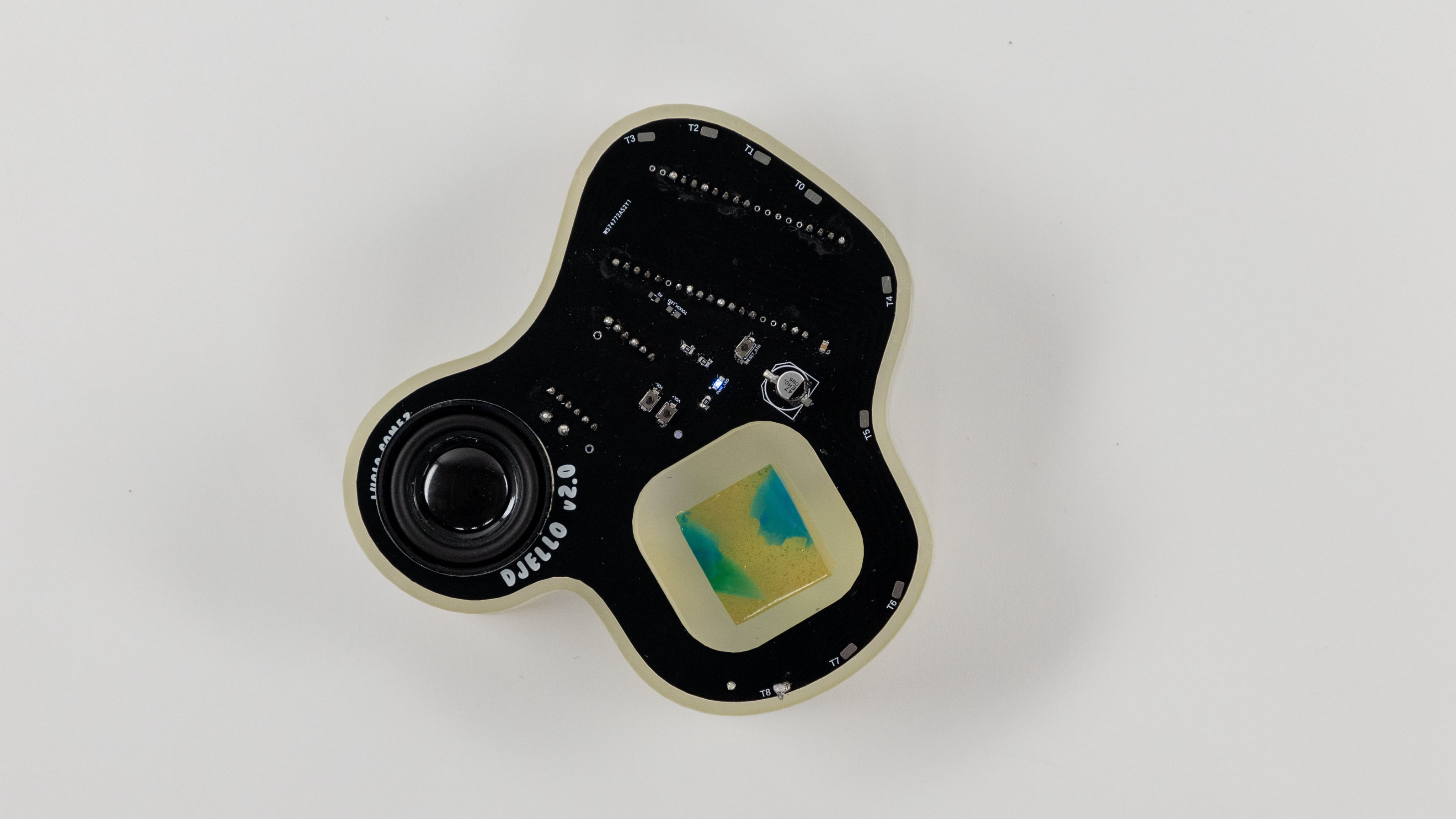
Last semester I created DJELLO, a colorful gelatin synth where users touch pieces of Jello to generate sounds that complement the squishy material. I’ve continued to build on that concept in collaboration with Solid Wiggles, a boutique Jello shot company in Brooklyn. During the past two months I designed and fabricated DJELLO 2.0, a printed circuit board that functions as an interactive serving platter for a Solid Wiggles jelly shot.
 [DJELLO 2.0]
The benefit of using a printed circuit board is that it’s self-contained; there are no messy wires going to a breadboard or my laptop. While this is necessary for making DJELLO 2.0 more durable, portable, and polished, it means that I can’t rely on speakers or music-making software on my laptop to handle the sound interactions. Some requirements for this standalone circuit board were
- Sound file storage
- Built-in speaker loud enough to hear in a crowded room
- Battery powered
- Able to hold a Solid Wiggles jelly shot
- Reliable capacitive touch sensor
- Reset button to recalibrate sensors to current Jello consistency
In discussion with Solid Wiggles we also decided to allow for one-to-one and one-to-many use cases
- One-to-one: A single jelly shot sitting on the circuit board, hooked up to capacitive touch with no visible wires. Touching it produces a random jelly-like sound
- One-to-many: Extra wires can be soldered onto DJELLO 2.0 to let it simultaneously support as many jellies as possible. Each jelly produces a distinct, consistent sound
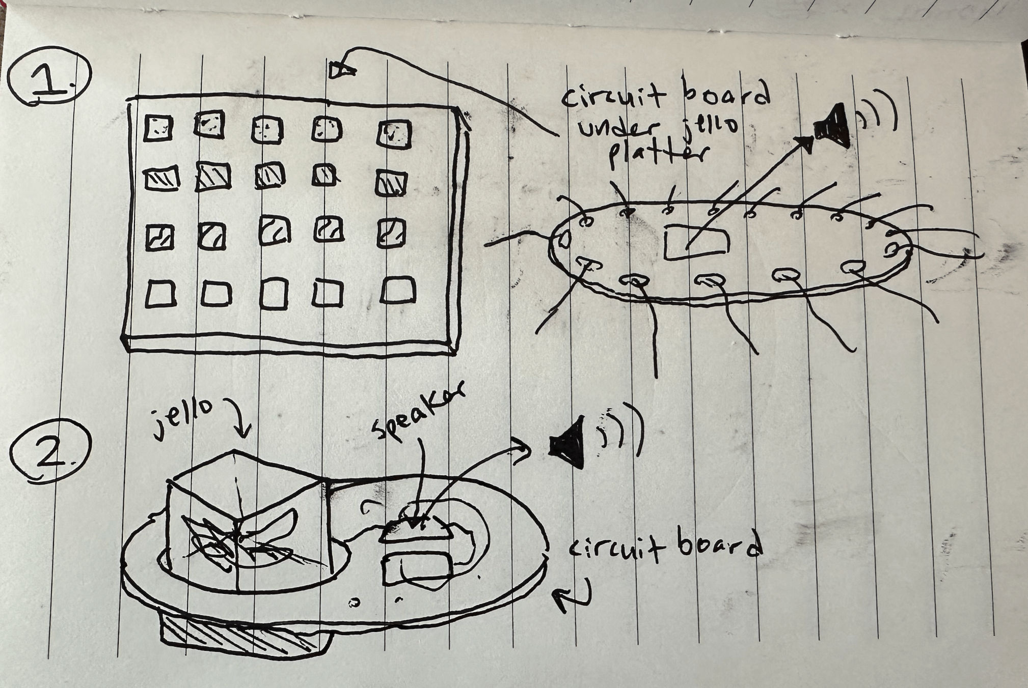 [Initial sketch demonstrating (1) one-to-many and (2) one-to-one modes]
Components
I researched components that would help me achieve the above requirements. I landed on a popular ESP-32 development board because it provides 10 built-in capacitive touch sensors, so support for 10 jellies. It also supports Bluetooth in case I want to explore that in the future.
For storing and playing sound files, I came across the DFPlayerPro. I chose it compared to the Mini DFPlayer because it has 128MB of on-board storage, no microSD card required, and an audio amplifier. I can directly connect it to my laptop to put audio files onto it via USB-C. After wiring output to a small speaker, it works perfectly with no fuss.
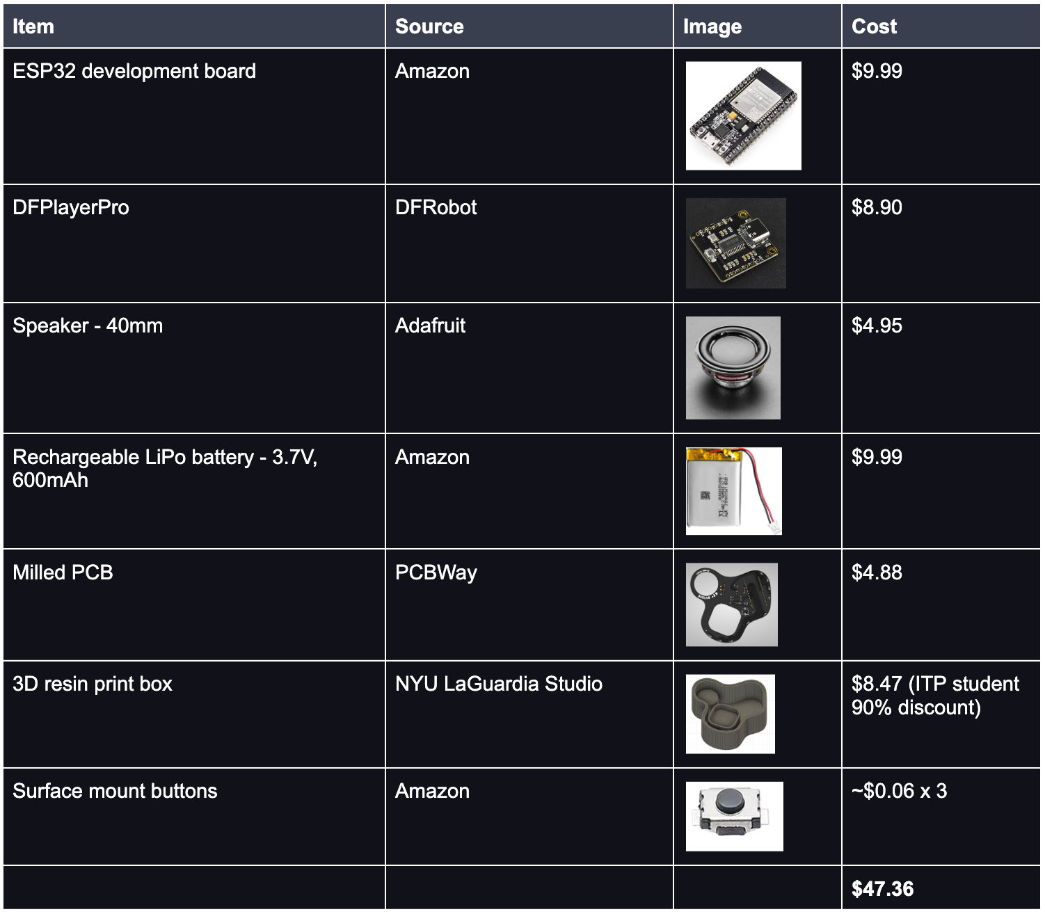
Below are all the parts I purchased to build DJELLO 2.0, for a total of $47.36. That’s not including some hefty shipping costs for overseas parts + any prototype materials, i.e. copper proto boards. This list also doesn’t include the tiny surface mount circuit board components that my grad program provides.
Prototyping
After I settled on my component list I began to prototype. My first prototype was on a breadboard so I could understand how everything needed to connect. I powered the breadboard from the lipo battery, connected the ESP32 and MP3 player via serial communication, and wired a speaker coming out of the MP3 player. And of course, stuck a wire into a Jello cup to test the ESP32’s capacitive touch abilities.
[DJELLO 2.0 breadboard prototype - no external wires going to a laptop]
The main challenge I ran into was misunderstanding how to wire UART serial communication between two boards. UART is how the ESP32 and the DFPlayerPro communicate with each other, for example
- The ESP32 touch sensors recognize a Jello touch and need to tell the DFPlayerPro to start playing a sound
- The DFPlayerPro needs to tell the ESP32 that it’s alive when the board first powers on
- The ESP32 asks the DFPlayerPro for its current volume level
Both devices need to send and receive data to and from each other. So the TX (transmitter) pin on one board should be connected to the RX (receiver) pin on the other board. I was mistakenly connecting TX to TX and RX to RX which prevented the boards from communicating with each other. I was super stuck on this until I swapped the wires by accident and my prototype started to work!
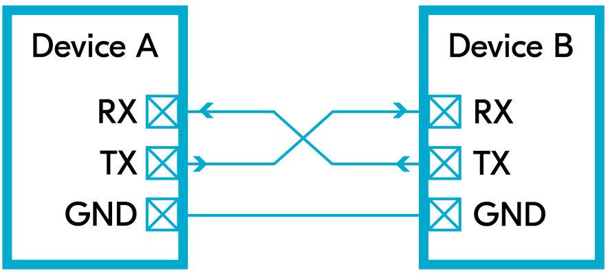 [Diagram of how UART serial communication should be wired]
Circuit Board Design
With a working breadboard prototype, I moved onto the Autodesk Fusion schematic and board layout so I could mill a prototype PCB at school. I went over the details of this in a previous blog post, but this time there were some extra steps. Namely, creating custom components for the ESP32 and DFPlayerPro and designing a double sided board.
Creating custom components meant looking at the physical dimensions of my boards and their pins, and recreating that in Fusion. Getting the dimensions wrong would mean the board won’t fit in my design. I also had to take care to name each pin correctly based on the physical board layout. If I swapped the power and ground pins, for example, that could fry the board.
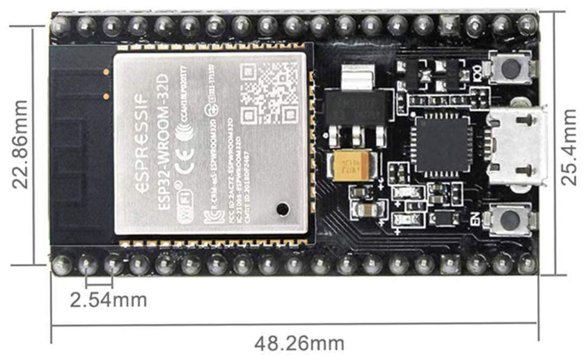 [Dimensions for the ESP32 development board]
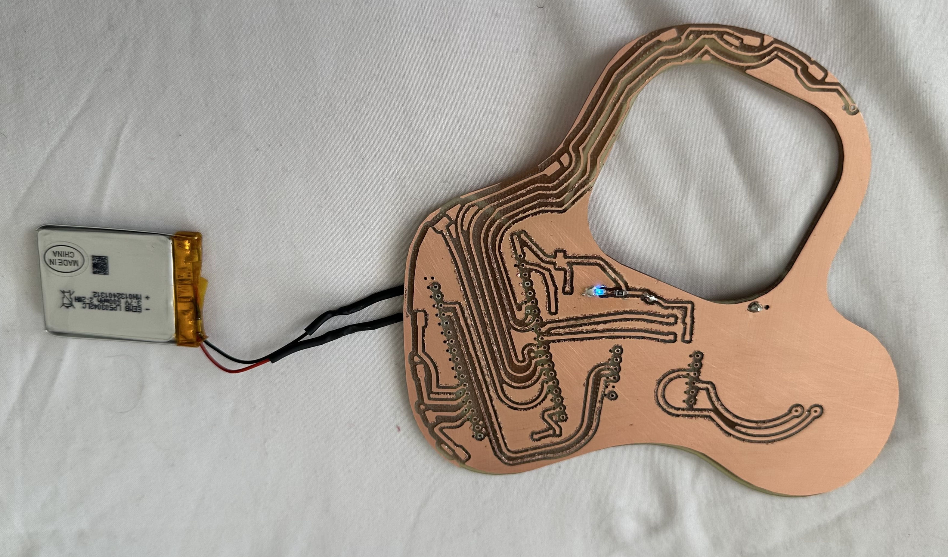
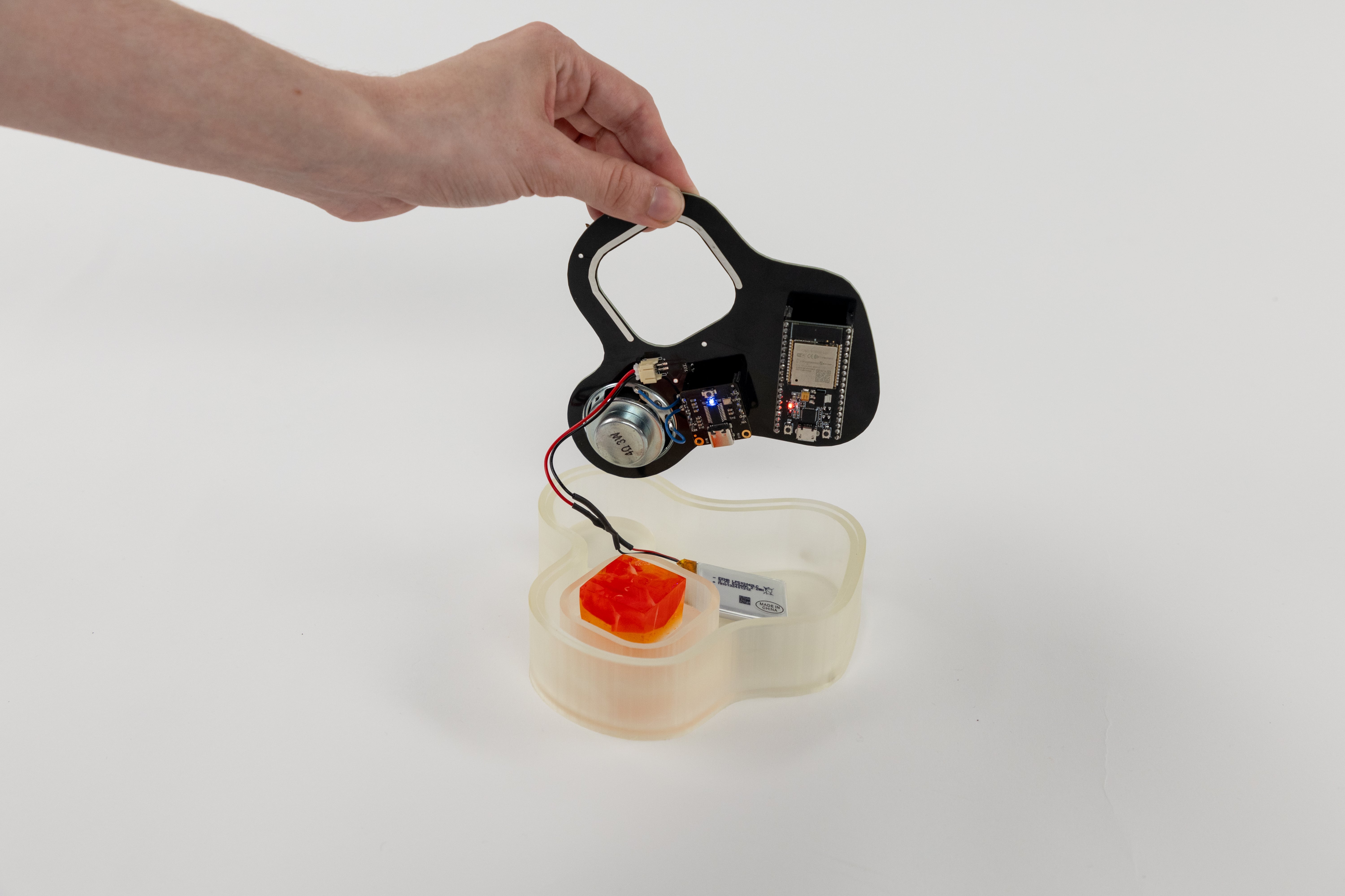
Figuring out an organized board layout was a major challenge for me. The board needed to be double sided, with components soldered to both sides. I mainly needed the battery connector soldered to the bottom side so that the battery could be hidden in the 3D printed box, with the circuit board acting as the box’s lid. This was key for the board being portable with no exposed wires. However, if the battery is connected to the board’s bottom layer of copper, then the power signal needs a way to reach the top layer of copper to power everything up there.
 [The battery is plugged into the bottom of the board, but the top of the board successfully shows a blue power indicator]
The solution to this is to add vias, small holes that are drilled through the board and can be filled with a conductive material to route the signal between two planes. I grew up on Star Trek so this reminds me of a wormhole in space! I used a few vias to route power and ground back and forth between the top and bottom layer. This simplifies the board design because instead of having to carefully route thin wires around tons of components, I could kind of cheat by creating these wormhole shortcuts through the board.
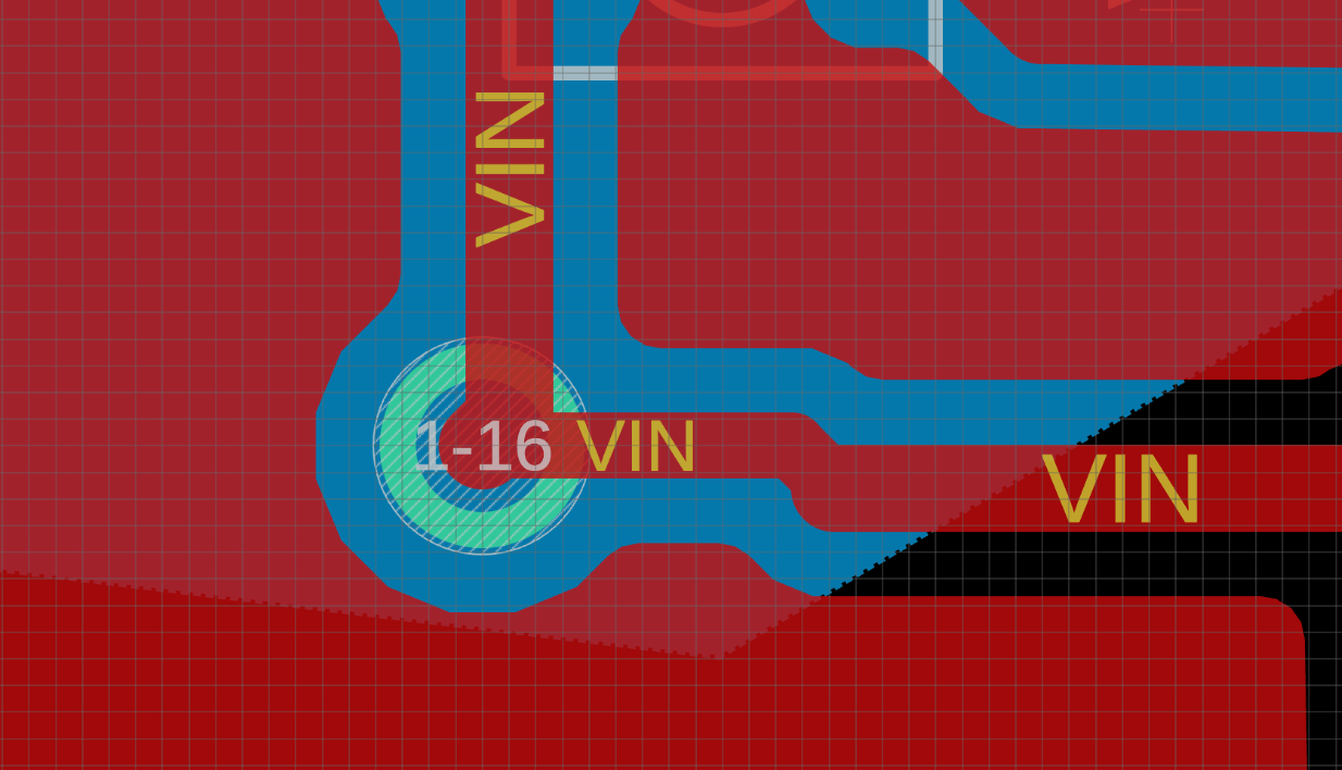 [A power via, where the VIN power signal comes up from the blue bottom layer to the red top layer]
I did something similar for attaching the ESP32 and DFPlayerPro to the circuit board. I planned to have them on the bottom side of the board, so they’d be hidden inside of the 3D printed box along with the battery. Solely because I didn’t want them sticking up from the surface and getting in the way of the Jello on top.
I added throughholes that I could solder the smaller boards’ pins to, so they’d connect to the main circuit on the top of the board. This required some mental spatial gymnastics, because I had to mirror the components in the design to simulate the act of physically rotating a board to place it upside down relative to the top bird’s eye view of the board.
 [The bottom side of my prototype board, with the battery connector, ESP32, and DFPlayerPro]
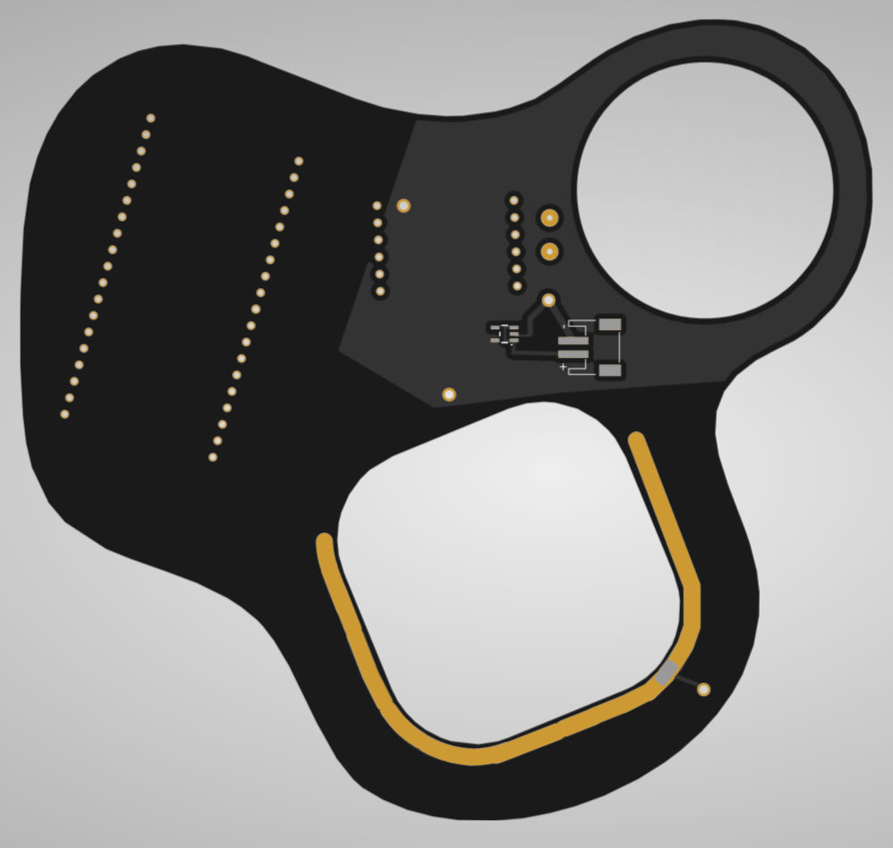
Here’s the top (red) and bottom (blue) of my board. Any green circles are vias or throughholes that pass through both board layers. The design includes cutouts for the speaker and the Jello platter hole, inside of a fun blobby outline. I designed the board shape in Adobe Illustrator and imported it into my Fusion design.
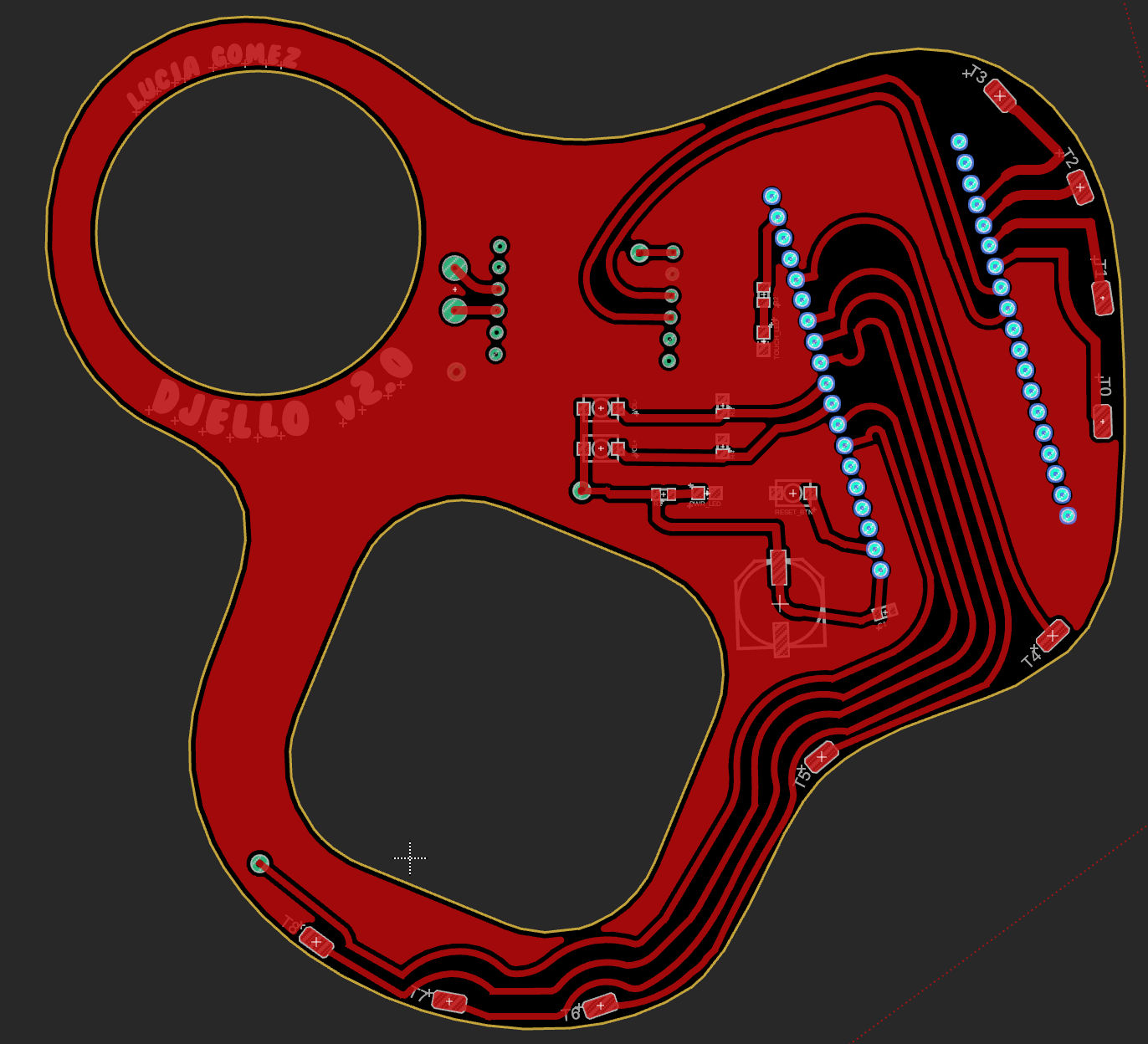 |
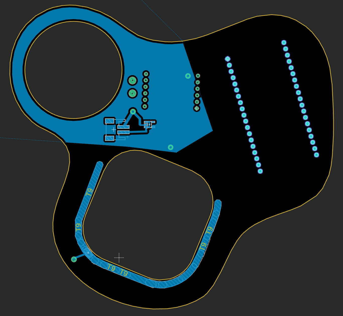 |
[Top (red) and bottom (blue) of my board layout]
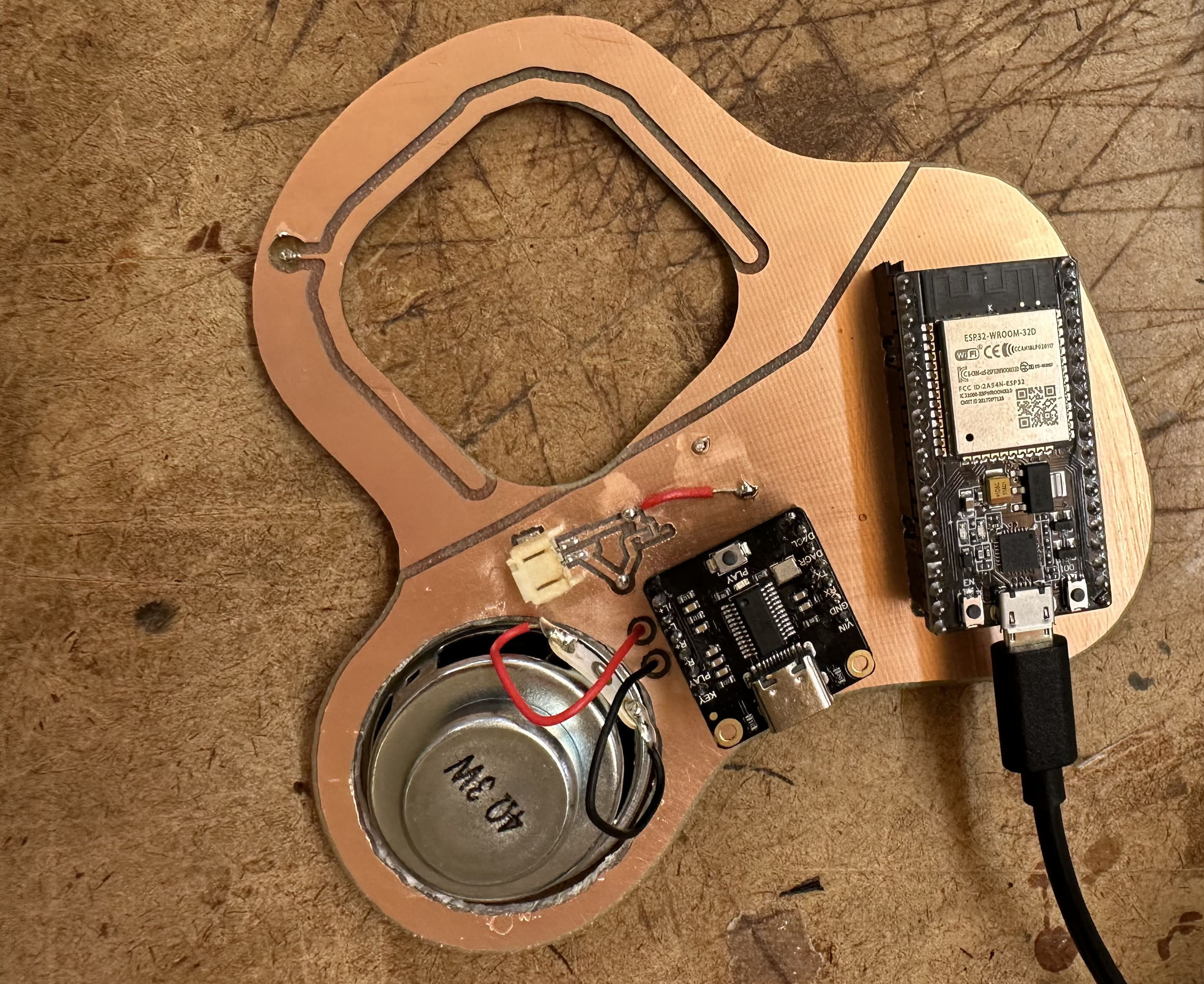
I milled and assembled this board design, whipped up a 3D printed box, uploaded some code, and I eventually had a working PCB prototype! I kept the volume and reset buttons off of this version because they were difficult to solder without causing electrical shorts. Before powering on my board I always tested for surprise connections between power and ground. A bit of solder that spread too far or a loose flake of copper leftover from milling can (and certainly did) cause a short.
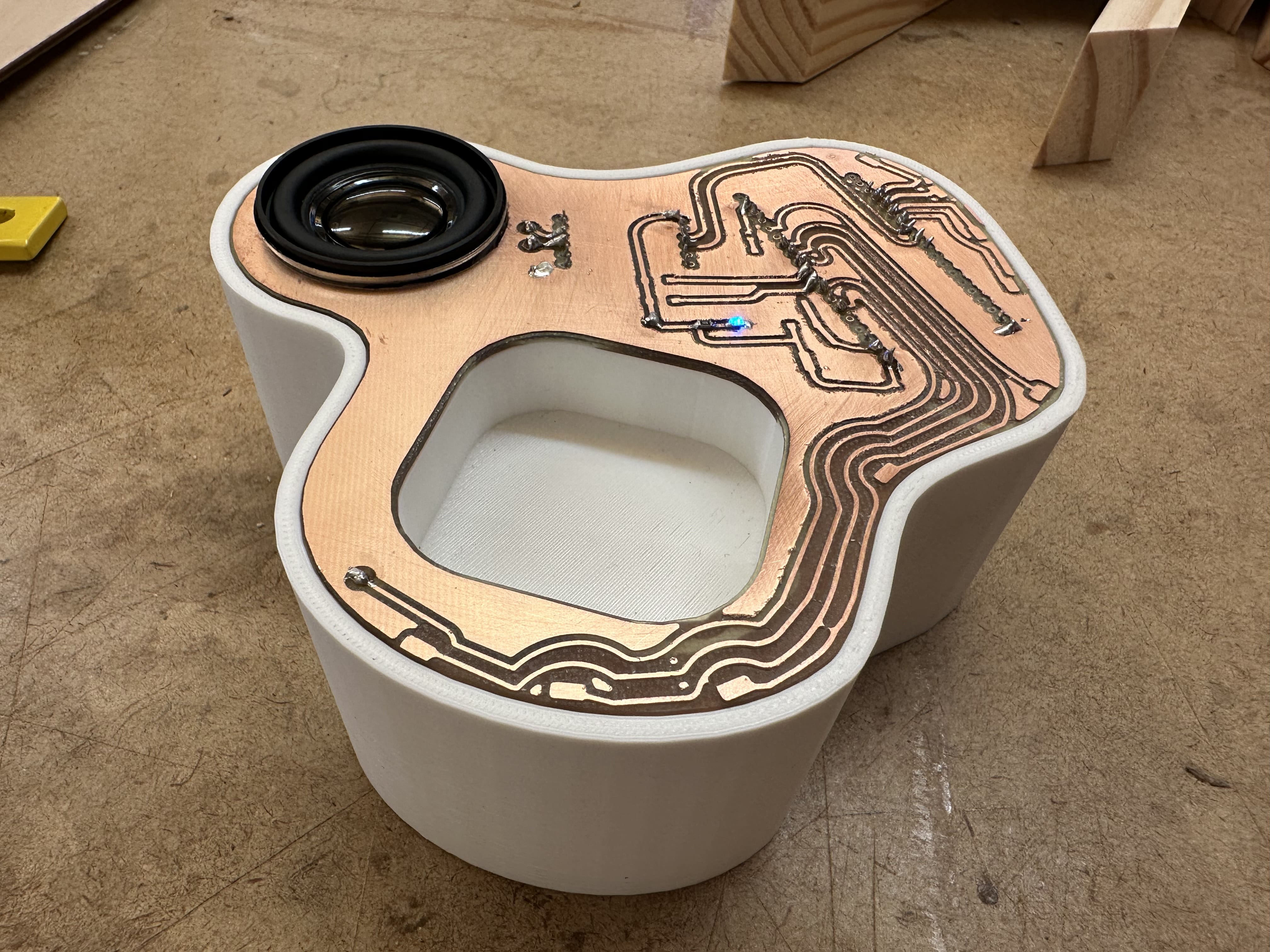 [My finished prototype board]
Final Board
My ultimate goal for this class, Homemade Hardware, was to order my final boards from a real manufacturer. I wanted to understand the process of preparing my board files for the real world so that I can potentially keep working on PCBs after I leave ITP and all its expensive shop equipment. Professionally manufactured boards also look much nicer than the shitty pieces of copper I milled, so I wanted that extra level of polish for DJELLO 2.0.
I placed an order with PCBWay. They were surprisingly cheap at ~$5/board, so I ordered 10. I could have a whole fleet of DJELLOs one day… if I gather 10x the required components for ~$500. PCBWay made the ordering process fairly straightforward, and their online board viewer reassured me that my board files were in good shape.
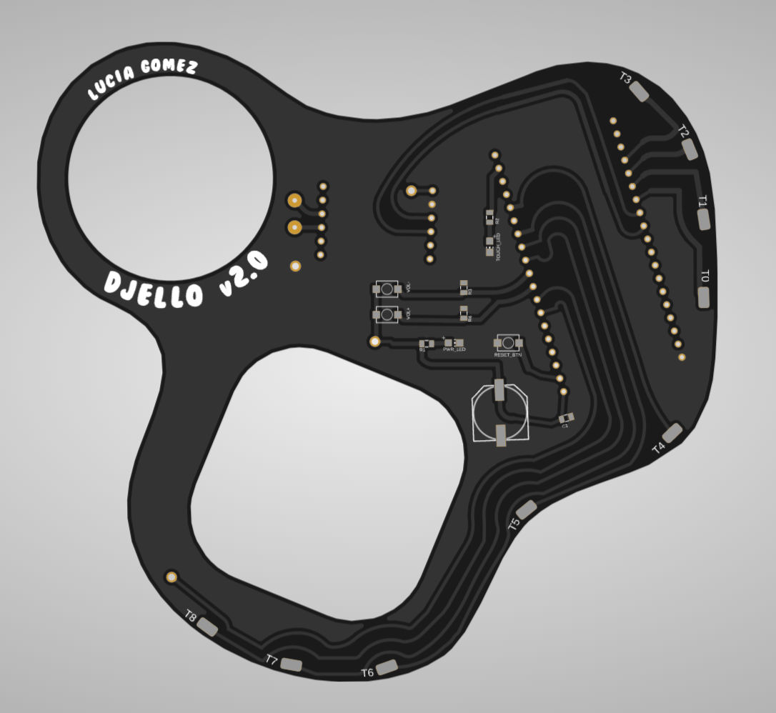 |
 |
[Top (left) and bottom (right) previews of my board on PCBWay]
My boards arrived within one week and looked exactly as I expected! Some assembly required of course. The black solder mask looks much nicer than the bare copper on my prototype. They sit perfectly flush in the 3D printed box, and snap in with a nice click.
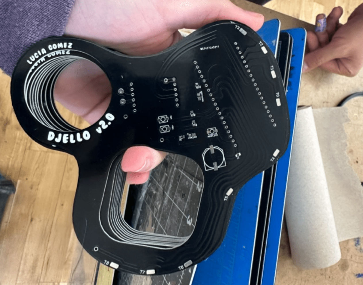 [My PCBs that arrived in the mail]
One small oopsie on my part was not testing all of the ESP32’s capacitive touch sensors before finalizing my design. It’s advertised as having 10 touch sensors, but upon testing I learned that only 8 are functional. While the ESP32 chip itself has 10 touch sensors, most development boards that incorporate this chip only enable 8. Oh well, my PCB has 2 dead touch sensors and can only support 8 jellies.
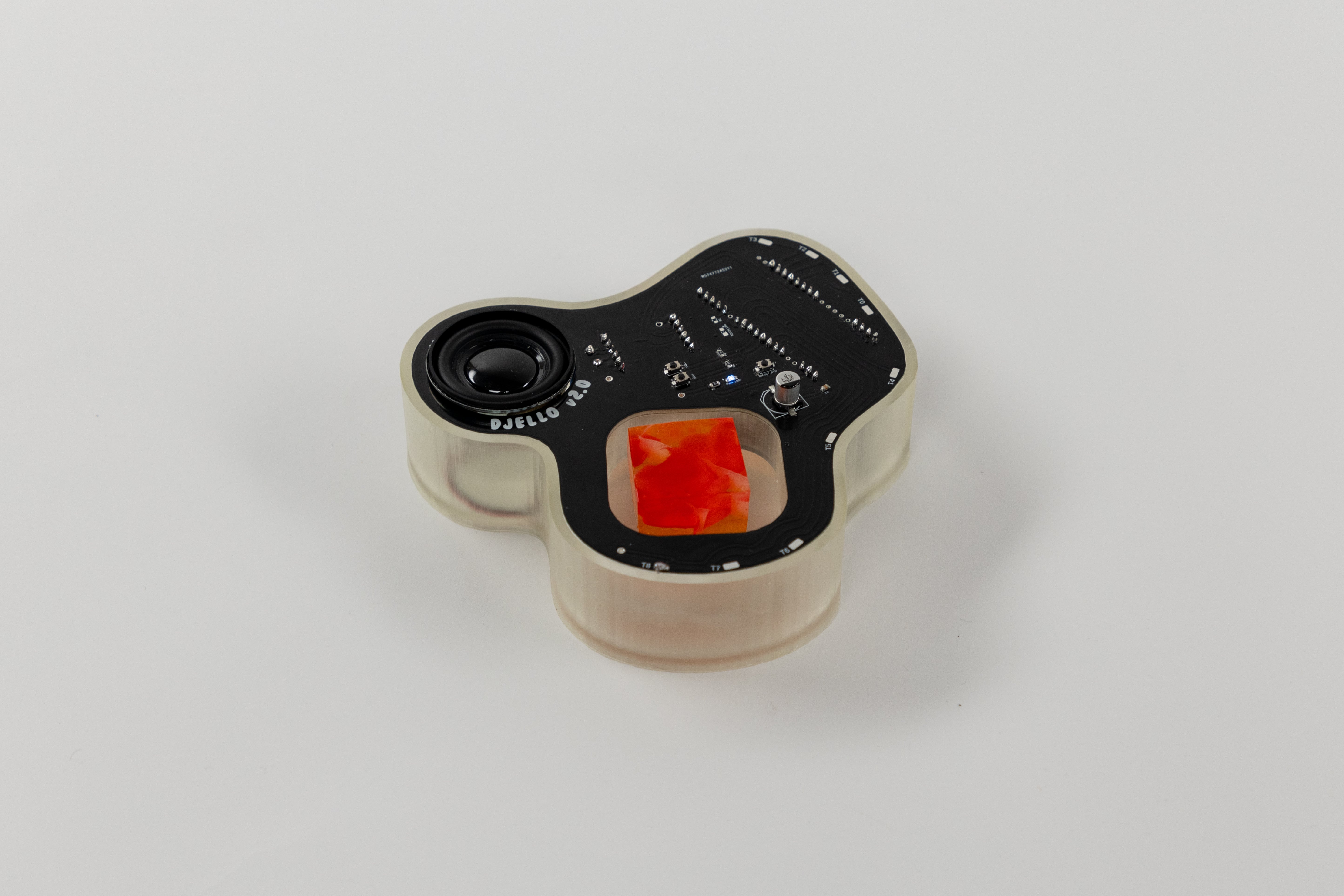
Overall I’m very happy with how DJELLO 2.0 turned out, and how the Solid Wiggles jelly shots look in it! The speaker quality in conjunction with the adjustable volume is good for crowded rooms. The 3D printed resin box was a first for me, but I’m glad I went with that design choice. The ESP32 and DFPlayerPro’s built-in LEDs can glow and diffuse through the resin. I may add some extra colored Neopixel lights in there that respond to sound or touch.
 |
 |
 |